What is the Constant Power Design of LED Driver?
Driving LED by constant power mode has recently been a popular topic. Why do LEDs must be driven by the constant current? Why not with a constant power source?
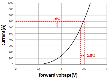
Before discussing the above issue, we must understand why the LED must be driven by a constant current. As shown in Figure (a) LED I-V curve, when the LED forward voltage changed about 2.5%, the current through the LED will correspondingly change about 16%, and forward voltage of the LED is easily affected by junction temperature. The change of high and low temperature may even make the voltage change as high as 20% or more. The brightness of the LED is proportional to the forward current of the LED. If the current varies in big scale, so is the brightness. Therefore, LED must be driven by a constant current source. However, can the LED be driven by constant power? To further discuss this topic, first, we should neglect whether constant power is equivalent to constant brightness or not. Via I-V and temperature curve of LED, the design of a constant power driver seems workable. If the answer is yes, why do LED driver manufacturers not develop the constant power LED driver? It is not difficult to design a driver with constant power design as long as the implementation of the MCU ( Micro Controller Unit ) is carried out in LED driver, which control output power refers to the PWM ( Pulse Width Modulation )duty cycle.
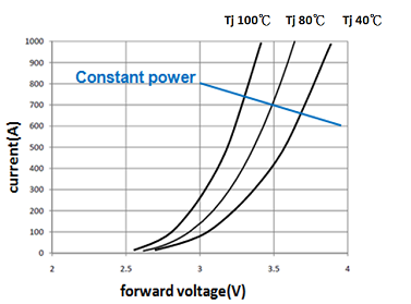
In order to control PWM duty cycle, the microcontroller is in charge of the calculation between feedback signals of the output voltage and current and drives the output to refer to constant power curve in blue of Figure (b), so that the constant power output can be achieved. However, to manufacture a constant power led driver not only cost a certain amount of money but also causing another issue that the output current will increase due to the damage of LED, which can further make the situation even worse. As the LED is a negative temperature coefficient component, reducing the output current to maintain the high life performance of the LED is expected when the temperature is higher. Nevertheless, the constant power method is in conflict with this consideration. The constant power design LED driver will increase the output current refer to lower output voltage for high-temperature application. In sum, considering various factors, providing “ resemble constant power” led driver with a wide range of output voltage and current is the most effective solution.
The constant power LED drivers made by MEAN WELL are specially designed, providing customers with a wide range of voltage and current. To avoid unnecessary cost due to over-design, the misusage because of LED’s characteristic, and causing damage to the lamps, offering a wide range, resemble constant power is currently the most sufficient solution.
 |
 |
|
Figure (a) LED I-V curve
|
Figure (b) LED I-V curve with junction temperature |
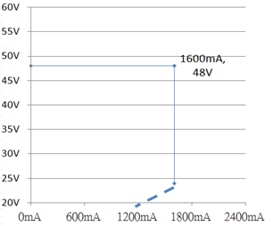
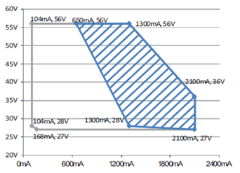
The whole XLG series is designed with constant power topology. A wide range of output voltage and current provides a flexible and efficient solution for different configuration of led, which can also reduce the number of models for inventory. Take the comparison of ELG-75-48/ XLG-75-H for an example, Max. power of ELG-75-48 will be at 48V/1.56A refer to curve(c). When a led voltage is much lower than 48V, output current can’t correspondingly be increased due to the design limitation. Thus, the rated output power can’t be reached due to the voltage difference, while the XLG-75-H model easily avoids this issue. With the constant power design, the XLG-75-H provides full power at voltage range between 36V to 58V. Customers are capable to adjust output current and design led luminaires with full power refer to curve (d). Moreover, to achieve a led driver with a wide range of full power, XLG series use higher rated components and verification requirements in order to achieve higher reliability and lifetime. The wide adjustment range characteristic of XLG also makes it easier for customers during self-adjustment. For further information, please refer to the specification.
 |
 |
| Figure (c) I-V curve of ELG-75-H | Figure (d) I-V curve of XLG-75-H |
